
The material editor is a great tool for artists to create shaders thanks to its node-based system. However, it does have its limitations. For example, you cannot create things such as loops and switch statements.
Luckily, you can get around these limitations by writing your own code. To do this, you can create a Custom node which will allow you to write HLSL code.
In this tutorial, you will learn how to:
- Create a Custom node and set up its inputs
- Convert material nodes to HLSL
- Edit shader files using an external text editor
- Create HLSL functions
To demonstrate all of this, you will use HLSL to desaturate the scene image, output different scene textures and create a Gaussian blur.
The tutorial also assumes you are familiar with a C-type language such as C++ or C#. If you know a syntactically similar language such as Java, you should still be able to follow along.
- Part 1: Cel Shading
- Part 2: Toon Outline
- Part 3: Custom Shaders Using HLSL (you are here!)
Getting Started
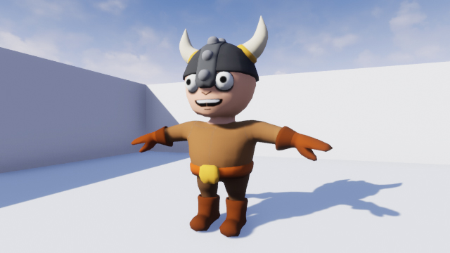
Start by downloading the materials for this tutorial (you can find a link at the top or bottom of this tutorial). Unzip it and navigate to CustomShadersStarter and open CustomShaders.uproject. You will see the following scene:
First, you will use HLSL to desaturate the scene image. To do this, you need to create and use a Custom node in a post process material.
Creating a Custom Node
Navigate to the Materials folder and open PP_Desaturate. This is the material you will edit to create the desaturation effect.
First, create a Custom node. Just like other nodes, it can have multiple inputs but is limited to one output.

Next, make sure you have the Custom node selected and then go to the Details panel. You will see the following:
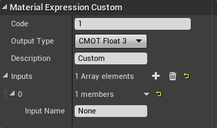
Here is what each property does:
- Code: This is where you will put your HLSL code
- Output Type: The output can range from a single value (CMOT Float 1) up to a four channel vector (CMOT Float 4).
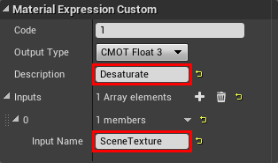
- Description: The text that will display on the node itself. This is a good way to name your Custom nodes. Set this to Desaturate.
- Inputs: This is where you can add and name input pins. You can then reference the inputs in code using their names. Set the name for input 0 to SceneTexture.
To desaturate the image, replace the text inside Code with the following:
return dot(SceneTexture, float3(0.3,0.59,0.11));
dot() is an intrinsic function. These are functions built into HLSL. If you need a function such as atan() or lerp(), check if there is already a function for it.
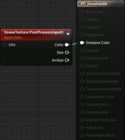
Finally, connect everything like so:
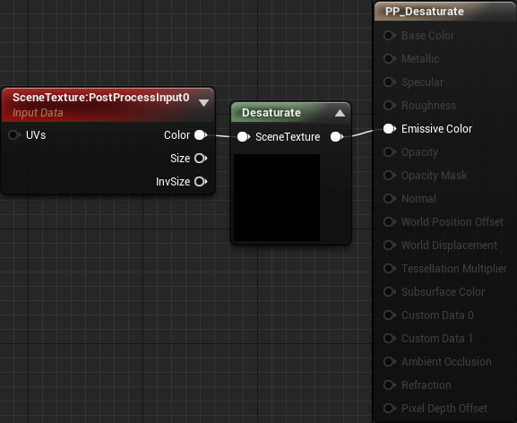
Summary:
- SceneTexture:PostProcessInput0 will output the color of the current pixel
- Desaturate will take the color and desaturate it. It will then output the result to Emissive Color
Click Apply and then close PP_Desaturate. The scene image is now desaturated.

You might be wondering where the desaturation code came from. When you use a material node, it gets converted into HLSL. If you look through the generated code, you can find the appropriate section and copy-paste it. This is how I converted the Desaturation node into HLSL.
In the next section, you will learn how to convert a material node into HLSL.
Converting Material Nodes to HLSL
For this tutorial, you will convert the SceneTexture node into HLSL. This will be useful later on when you create a Gaussian blur.
First, navigate to the Maps folder and open GaussianBlur. Afterwards, go back to Materials and open PP_GaussianBlur.
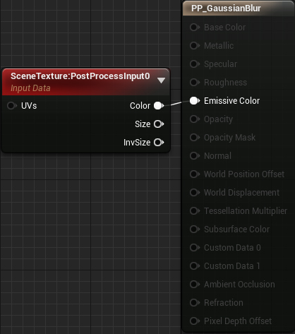
Unreal will generate HLSL for any nodes that contribute to the final output. In this case, Unreal will generate HLSL for the SceneTexture node.
To view the HLSL code for the entire material, select Window\HLSL Code. This will open a separate window with the generated code.
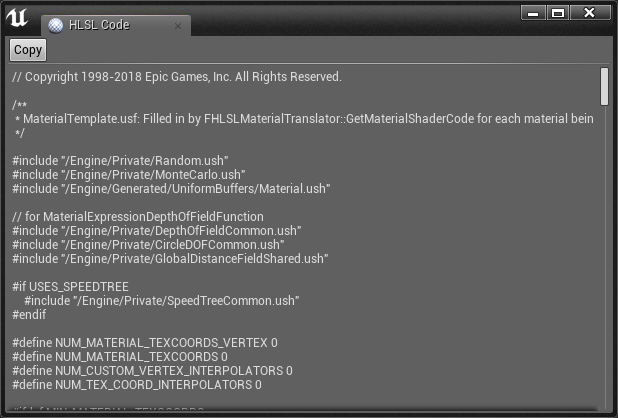

Since the generated code is a few thousand lines long, it’s quite difficult to navigate. To make searching easier, click the Copy button and paste it into a text editor (I use Notepad++). Afterwards, close the HLSL Code window.
Now, you need to find where the SceneTexture code is. The easiest way to do this is to find the definition for CalcPixelMaterialInputs(). This function is where the engine calculates all the material outputs. If you look at the bottom of the function, you will see the final values for each output:
PixelMaterialInputs.EmissiveColor = Local1;
PixelMaterialInputs.Opacity = 1.00000000;
PixelMaterialInputs.OpacityMask = 1.00000000;
PixelMaterialInputs.BaseColor = MaterialFloat3(0.00000000,0.00000000,0.00000000);
PixelMaterialInputs.Metallic = 0.00000000;
PixelMaterialInputs.Specular = 0.50000000;
PixelMaterialInputs.Roughness = 0.50000000;
PixelMaterialInputs.Subsurface = 0;
PixelMaterialInputs.AmbientOcclusion = 1.00000000;
PixelMaterialInputs.Refraction = 0;
PixelMaterialInputs.PixelDepthOffset = 0.00000000;
Since this is a post process material, you only need to worry about EmissiveColor. As you can see, its value is the value of Local1. The LocalX variables are local variables the function uses to store intermediate values. If you look right above the outputs, you will see how the engine calculates each local variable.
MaterialFloat4 Local0 = SceneTextureLookup(GetDefaultSceneTextureUV(Parameters, 14), 14, false);
MaterialFloat3 Local1 = (Local0.rgba.rgb + Material.VectorExpressions[1].rgb);
The final local variable (Local1 in this case) is usually a “dummy” calculation so you can ignore it. This means SceneTextureLookup() is the function for the SceneTexture node.
Now that you have the correct function, let’s test it out.
Using the SceneTextureLookup Function
First, what do the parameters do? This is the signature for SceneTextureLookup():
float4 SceneTextureLookup(float2 UV, int SceneTextureIndex, bool Filtered)
Here is what each parameter does:
- UV: The UV location to sample from. For example, a UV of (0.5, 0.5) will sample the middle pixel.
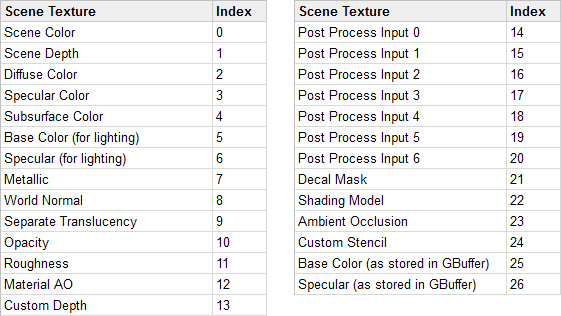
- SceneTextureIndex: This will determine which scene texture to sample from. You can find a table of each scene texture and their index below. For example, to sample Post Process Input 0, you would use 14 as the index.
- Filtered: Whether the scene texture should use bilinear filtering. Usually set to false.
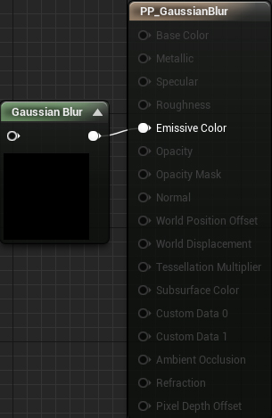
To test, you will output the World Normal. Go to the material editor and create a Custom node named Gaussian Blur. Afterwards, put the following in the Code field:
return SceneTextureLookup(GetDefaultSceneTextureUV(Parameters, 8), 8, false);
This will output the World Normal for the current pixel. GetDefaultSceneTextureUV() will get the UV for the current pixel.
GetDefaultSceneTextureUV() and supply your desired index.
This is an example of how custom HLSL can break between versions of Unreal.
Next, disconnect the SceneTexture node. Afterwards, connect Gaussian Blur to Emissive Color and click Apply.
At this point, you will get the following error:
[SM5] /Engine/Generated/Material.ush(1410,8-76): error X3004: undeclared identifier 'SceneTextureLookup'
This is telling you that SceneTextureLookup() does not exist in your material. So why does it work when using a SceneTexture node but not in a Custom node? When you use a SceneTexture, the compiler will include the definition for SceneTextureLookup(). Since you are not using one, you cannot use the function.
Luckily, the fix for this is easy. Set the SceneTexture node to the same texture as the one you are sampling. In this case, set it to WorldNormal.
Afterwards, connect it to the Gaussian Blur. Finally, you need to set the input pin’s name to anything besides None. For this tutorial, set it to SceneTexture.
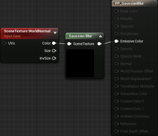
Now the compiler will include the definition for SceneTextureLookup().
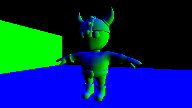
Click Apply and then go back to the main editor. You will now see the world normal for each pixel.
Right now, editing code in the Custom node isn’t too bad since you are working with little snippets. However, once your code starts getting longer, it becomes difficult to maintain.
To improve the workflow, Unreal allows you to include external shader files. With this, you can write code in your own text editor and then switch back to Unreal to compile.
Using External Shader Files
First, you need to create a Shaders folder. Unreal will look in this folder when you use the #include directive in a Custom node.
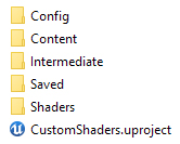
Open the project folder and create a new folder named Shaders. The project folder should now look something like this:
Next, go into the Shaders folder and create a new file. Name it Gaussian.usf. This is your shader file.
Open Gaussian.usf in a text editor and insert the code below. Make sure to save the file after every change.
return SceneTextureLookup(GetDefaultSceneTextureUV(Parameters, 2), 2, false);
This is the same code as before but will output Diffuse Color instead.
To make Unreal detect the new folder and shaders, you need to restart the editor. Once you have restarted, make sure you are in the GaussianBlur map. Afterwards, reopen PP_GaussianBlur and replace the code in Gaussian Blur with the following:
#include "/Project/Gaussian.usf"
return 1;
Now when you compile, the compiler will replace the first line with the contents of Gaussian.usf. Note that you do not need to replace Project with your project name.
Click Apply and then go back to the main editor. You will now see the diffuse colors instead of world normals.

Now that everything is set up for easy shader development, it’s time to create a Gaussian blur.
Creating a Gaussian Blur
Just like in the toon outlines tutorial, this effect uses convolution. The final output is the average of all pixels in the kernel.
In a typical box blur, each pixel has the same weight. This results in artifacts at wider blurs. A Gaussian blur avoids this by decreasing the pixel’s weight as it gets further away from the center. This gives more importance to the center pixels.
Convolution using material nodes is not ideal due to the number of samples required. For example, in a 5×5 kernel, you would need 25 samples. Double the dimensions to a 10×10 kernel and that increases to 100 samples! At that point, your node graph would look like a bowl of spaghetti.
This is where the Custom node comes in. Using it, you can write a small for loop that samples each pixel in the kernel. The first step is to set up a parameter to control the sample radius.
Creating the Radius Parameter
First, go back to the material editor and create a new ScalarParameter named Radius. Set its default value to 1.

The radius determines how much to blur the image.
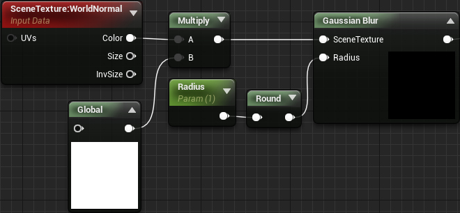
Next, create a new input for Gaussian Blur and name it Radius. Afterwards, create a Round node and connect everything like so:
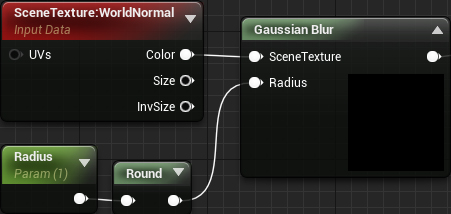
The Round is to ensure the kernel dimensions are always whole numbers.
Now it’s time to start coding! Since you need to calculate the Gaussian twice for each pixel (vertical and horizontal offsets), it’s a good idea to turn it into a function.
When using the Custom node, you cannot create functions in the standard way. This is because the compiler copy-pastes your code into a function. Since you cannot define functions within a function, you will receive an error.
Luckily, you can take advantage of this copy-paste behavior to create global functions.
Creating Global Functions
As stated above, the compiler will literally copy-paste the text in a Custom node into a function. So if you have the following:
return 1;
The compiler will paste it into a CustomExpressionX function. It doesn’t even indent it!
MaterialFloat3 CustomExpression0(FMaterialPixelParameters Parameters)
{
return 1;
}
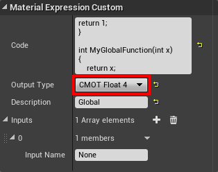
Look what happens if you use this code instead:
    return 1;
}

float MyGlobalVariable;

int MyGlobalFunction(int x)
{
    return x;
The generated HLSL now becomes this:
MaterialFloat3 CustomExpression0(FMaterialPixelParameters Parameters)
{
    return 1;
}

float MyGlobalVariable;

int MyGlobalFunction(int x)
{
    return x;
}
As you can see, MyGlobalVariable and MyGlobalFunction() are not contained within a function. This makes them global and means you can use them anywhere.
Now let’s use this behavior to create the Gaussian function.
Creating the Gaussian Function
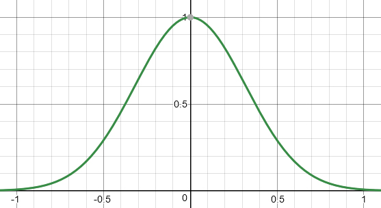
The function for a simplified Gaussian in one dimension is:
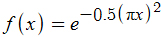
This results in a bell curve that accepts an input ranging from approximately -1 to 1. It will then output a value from 0 to 1.
For this tutorial, you will put the Gaussian function into a separate Custom node. Create a new Custom node and name it Global.
Afterwards, replace the text in Code with the following:
    return 1;
}

float Calculate1DGaussian(float x)
{
    return exp(-0.5 * pow(3.141 * (x), 2));
Calculate1DGaussian() is the simplified 1D Gaussian in code form.
To make this function available, you need to use Global somewhere in the material graph. The easiest way to do this is to simply multiply Global with the first node in the graph. This ensures the global functions are defined before you use them in other Custom nodes.
First, set the Output Type of Global to CMOT Float 4. You need to do this because you will be multiplying with SceneTexture which is a float4.
Next, create a Multiply and connect everything like so:
Click Apply to compile. Now, any subsequent Custom nodes can use the functions defined within Global.
The next step is to create a for loop to sample each pixel in the kernel.
Sampling Multiple Pixels
Open Gaussian.usf and replace the code with the following:
static const int SceneTextureId = 14;
float2 TexelSize = View.ViewSizeAndInvSize.zw;
float2 UV = GetDefaultSceneTextureUV(Parameters, SceneTextureId);
float3 PixelSum = float3(0, 0, 0);
float WeightSum = 0;
Here is what each variable is for:
- SceneTextureId: Holds the index of the scene texture you want to sample. This is so you don’t have to hard code the index into the function calls. In this case, the index is for Post Process Input 0.
- TexelSize: Holds the size of a texel. Used to convert offsets into UV space.
- UV: The UV for the current pixel
- PixelSum: Used to accumulate the color of each pixel in the kernel
- WeightSum: Used to accumulate the weight of each pixel in the kernel
Next, you need to create two for loops. One for the vertical offsets and one for the horizontal. Add the following below the variable list:
for (int x = -Radius; x <= Radius; x++)
{
    for (int y = -Radius; y <= Radius; y++)
    {

    }
}
Conceptually, this will create a grid centered on the current pixel. The dimensions are given by 2r + 1. For example, if the radius is 2, the dimensions would be (2 * 2 + 1) by (2 * 2 + 1) or 5×5.
Next, you need to accumulate the pixel colors and weights. To do this, add the following inside the inner for loop:
float2 Offset = UV + float2(x, y) * TexelSize;
float3 PixelColor = SceneTextureLookup(Offset, SceneTextureId, 0).rgb;
float Weight = Calculate1DGaussian(x / Radius) * Calculate1DGaussian(y / Radius);
PixelSum += PixelColor * Weight;
WeightSum += Weight;
Here is what each line does:
- Calculate the relative offset of the sample pixel and convert it into UV space
- Sample the scene texture (Post Process Input 0 in this case) using the offset
- Calculate the weight for the sampled pixel. To calculate a 2D Gaussian, all you need to do is multiply two 1D Gaussians together. The reason you need to divide by
Radiusis because the simplified Gaussian expects a value from -1 to 1. This division will normalizexandyto this range. - Add the weighted color to
PixelSum - Add the weight to
WeightSum
Finally, you need to calculate the result which is the weighted average. To do this, add the following at the end of the file (outside the for loops):
return PixelSum / WeightSum;
That’s it for the Gaussian blur! Close Gaussian.usf and then go back to the material editor. Click Apply and then close PP_GaussianBlur. Use PPI_Blur to test out different blur radiuses.
Limitations
Although the Custom node is very powerful, it does come with its downsides. In this section, I will go over some of the limitations and caveats when using it.
Rendering Access
Custom nodes cannot access many parts of the rendering pipeline. This includes things such as lighting information and motion vectors. Note that this is slightly different when using forward rendering.
Engine Version Compatibility
HLSL code you write in one version of Unreal is not guaranteed to work in another. As noted in the tutorial, before 4.19, you were able to use a TextureCoordinate to get scene texture UVs. In 4.19, you need to use GetDefaultSceneTextureUV().
Optimization
Here is an excerpt from Epic on optimization:
Using the custom node prevents constant folding and may use significantly more instructions than an equivalent version done with built in nodes! Constant folding is an optimization that UE4 employs under the hood to reduce shader instruction count when necessary.

For example, an expression chain of Time >Sin >Mul by parameter > Add to something can and will be collapsed by UE4 into a single instruction, the final add. This is possible because all of the inputs of that expression (Time, parameter) are constant for the whole draw call, they do not change per-pixel. UE4 cannot collapse anything in a custom node, which can produce less efficient shaders than an equivalent version made out of existing nodes.

As a result, it is best to only use the custom node when it gives you access to functionality not possible with the existing nodes.
Where to Go From Here?
You can download the completed project using the link at the top or bottom of this tutorial.
If you’d like to get more out of the Custom node, I recommend you check out Ryan Bruck’s blog. He has posts detailing how to use the Custom node to create raymarchers and other effects.
If there are any effects you’d like to me cover, let me know in the comments below!
The post Unreal Engine 4 Custom Shaders Tutorial appeared first on Ray Wenderlich.
Unreal Engine 4 Custom Shaders Tutorial published first on https://medium.com/@koresol
